If you imagine using a counter, such as in a stopwatch or a geiger counter, you need to have not only the "add one" input but also a "reset" input.
We can have a synchronous reset or an asynchronous reset. An asynchronous reset takes effect immediately. A synchronous reset has to be held down for one clock pulse.
The synchronous reset can seem a bit odd, in that the clock pulse is actually the "add one" line. So while the "reset" input is 1, the "add one" operation yields 0, rather than x+1. But a 'reset' by itself does nothing without a clock pulse.
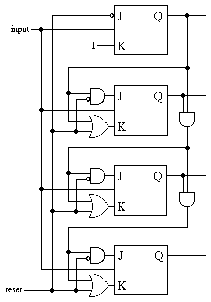
But a synchronous reset is easier to draw, so let's draw that. The following diagram is similar to the synchronous counter from the previous page.

To analyze this, consider the case where the 'reset' line is zero. (And let's ignore the unusual top flip flop, at first -- we'll deal with that separately, afterwards.) If 'reset' is zero, the 'J' inputs are being ANDed with 1, and the 'K' inputs are being ORed with 0. Each of these is the identity operation, so you can take out that reset line and the gates it's connected to... and then you'll see you simply have the synchronous counter from the previous page.
Therefore when 'reset' is zero, this functions as a simple synchronous counter.
Now consider when 'reset' is one (still ignoring the unusual top flip flop for now). The 'J' inputs are ANDed with 0, and the 'K' inputs are ORed with 1. This is the base law operation for those values: J will be 0 no matter what the other input is, and K will be 1 no matter what the other input is. This is the reset operation for an SR or JK flip-flop: the value of the flip-flop gets set to zero. So when the 'reset' input line is 1, a reset of all flip-flops occurs.
But what about the top flip-flop (representing the least-significant bit)? When 'reset' is zero, its inputs should be 1,1, because this bit always flips. When 'reset' is one, its inputs should be 0,1, just like they should be for the other (n-1) flip-flops. So the 'K' input should always be 1, and the 'J' input should be not-reset.
Ok, that's enough about counters for now. We still need to be able to make a general-purpose register, next.
This is part of the "counter and register notes" web pages, which contain the
following subtopics: