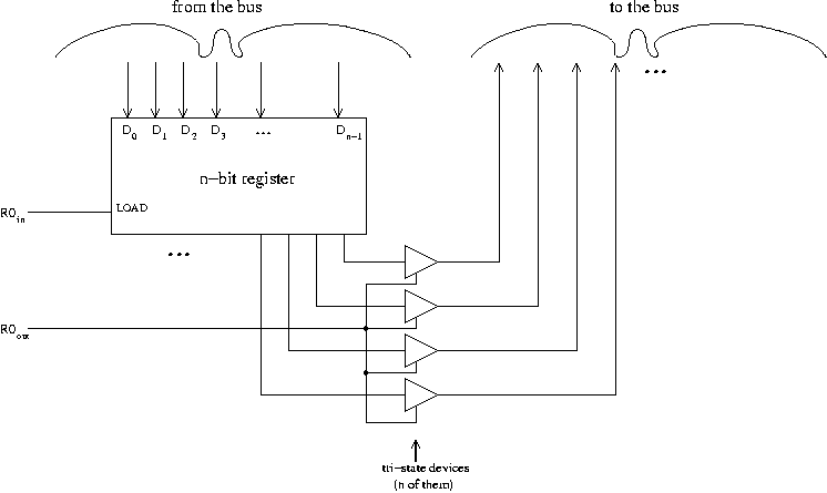
For input, i.e. the transfer of data from the bus to a register using a control signal such as R0in, there's no problem. The control line goes into the LOAD line of the register in question, and we just connect the bus into the data inputs of that register.
Outputs are different. We cannot have more than one register or other item outputting to the bus at the same time. This asymmetry between the status of inputs and outputs is the same as the principle in the circuit wiring we've been doing so far that you can't tie outputs together, even though you can tie inputs together.
Altogether, the device which the output of the register is going to pass through before being connected to the bus actually must have three possibilities:
We call such a thing a "tri-state device". We draw it like this:
(Different models of tri-state devices differ in whether the data, or control, or both, or neither, is inverted.)
In a tri-state device, when the control line is off, the output doesn't interfere with other outputs all tied together on the bus. So at all times we will have exactly one item outputting to the bus, by switching the control line on for that item's tri-state device and switching the control line off for all other items' tri-state devices. This is the purpose of the tri-state device.
On the other hand, there is no harm whatsoever in having multiple input lines on simultaneously. If we want to take what is in R0 and put it in both R1 and R2, we can use the control lines R0out, R1in, R2in.
To summarize, the connections between a register and the bus look like this:

This is the wiring for R0, R1, R2, and all the GPRs; also PC and MDR.
The IR, Y, and MAR registers only input from the bus, so they don't involve tristate devices.
The Z register only outputs to the bus; however, it still has a Zin control line attached to its LOAD control, so it differs from the above picture only in that the D inputs come from the ALU output rather than from the bus.
This is part of the "microprogramming notes" web pages, which contain the
following subtopics: